Cleveland SEL-30-TR User Manual
Browse online or download User Manual for Cookers Cleveland SEL-30-TR. Skillet TR Electric
- Page / 14
- Table of contents
- BOOKMARKS
- Cleveland 1
- TROUBLESHOOTING AND 3
- MAINTENANCE PROCEDURES 3
- SERVICE PARTS 4
- POWER TILT ASSEMBLY 5
- MANUAL TILT ASSEMBLY 6
- HYDRAULIC JACK ASSEMBLY 6
- KE003742 7
- PAN HINGE 10
- SHAFT ASSEMBLY 10
- FRAME / LID 11
- ASSMEBLY 11
- ELECTRICAL 12
- POWER TILT 12
- 14
- CE, CSA AND AGA 14
Summary of Contents
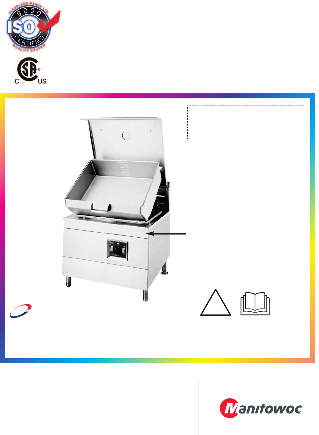
Maintenance Procedures& Parts ListsTR Electric Braising PanFor units built after August 2011SE95032 Rev. 7AMay 2012SEL-30-TRSEM-30-TRSEL-40-TRSEM-
ITEM NO. PART NO. DESCRIPTION QTY.1 FA20032 LOCK NUT 1/2-13 S.S. . . . . . . . . . . . . . . . . . . . . . . . . . . . . . . . . . . . . . . . . . .
ITEM NO. PART NO. DESCRIPTION QTY.1. SK2335499 LEG ASSEMBLY, FRONT . . . . . . . . . . . . . . . . . . . . . . . . . . . . . . . . . . . . . . . . .
ELECTRICAL BOXITEM NO. PART NO. DESCRIPTION QTY.1 KE53838-31 TRANSFORMER - POWER TILT, 208 - 480V . . . . . . . . . . . . . . . . . . . . . . . . . .
ITEM NO. PART NO. DESCRIPTION QTY.1. (SEL/SEM-30-TR) 2356306 ELEMENT - CENTER, 4.8KW, 600V. . . . . . . . . . . . . . . . . . . . . . . . . . . . .
WIRINGDIAGRAMCE, CSA AND AGA .
STATEMENT OF RESPONSIBILITIES /DÉCLARATION DES RESPONSABILITÉS /DECLARACIÓN DE RESPONSABILIDADESThis document is for use by experiencedand trained Qua
TROUBLESHOOTING ANDMAINTENANCE PROCEDURESThe following trouble shooting guide and maintenance proceduresare meant to be used by Qualified Service Tech
SERVICE PARTSWARRANTYOur Company supports a worldwide network of Maintenance and Repair Centers. Contact your nearest Maintenance and Repair
POWER TILT ASSEMBLYTO HYDRAULIC CYLINDER (PRESSURE PORT)TO HYDRAULICCYLINDER(BREATHING PORT)TO HYDRAULICPUMP (PORT B)TO HYDRAULICPUMP (PORT A)2249 51
ITEM PART # DESCRIPTION1 KE000523 HYDRAULIC JACK ASSY 12 KE53143 PLUG; 1/4-18 HYDRAULIC 13 KE55267 FLOW RESTRICTOR MT/TR 14 SK2379100 ELBOW;1/4-90D-
KE003742KE003740KE003741ITEM PART NUMBE
KE003742KE003740KE003741ITEM PART NUMBE
ITEM NO. PART NO. DESCRIPTION QTY.1 SK2474101 POWER SWITCH . . . . . . . . . . . . . . . . . . . . . . . . . . . . . . . . . . . . . . . . . . . . .
More documents for Cookers Cleveland SEL-30-TR

© 2020, manymanuals.com. All rights reserved. | 1.470 s |
 Manymanuals.com
 Manymanuals.de
 Manymanuals.fr
 Manymanuals.it
 Manymanuals.pl
 Manymanuals.cz
 Manymanuals.es
 Manymanuals-pt.com
Comments to this Manuals